
Leica Conversions Part II
The naming convention for early Leica camera models was different in Europe than in the US. I will stay with the European naming convention for this article; the list below provides the equivalent USmodels.
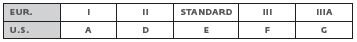
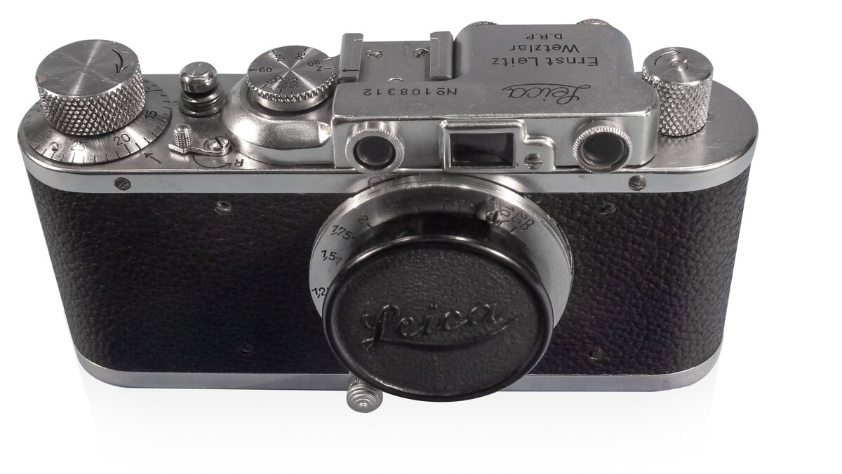
Image 1
TWO VERY DIFFERENT UPGRADES FOR EARLIER LEICAS TO III OR IIIA
Whenever new features in existing models or new models were released to the market, Leitz offered the possibility of applying the improvements to existing cameras and/or to convert them to the newest model. This was also the case when the Leica III, known as Model F in the US, was introduced. Conversions for screwmount Leicas were available until the late 50’s. Image A shows various conversion possibilities and their prices as of 1954 [1].
In this second article about Leica conversions, I will show two very different conversions to Leica III or IIIa. I will show which parts in each camera have been replaced during conversion (and why) and explain why these parts allow us to determine the time when conversion was done. As a reference camera I am taking a very early chrome plated Leica II, S/N 108312. This camera is in original condition with all parts from the time of production. Based on parts found in both of the converted cameras I assume that each of them was converted only once. (image 1)
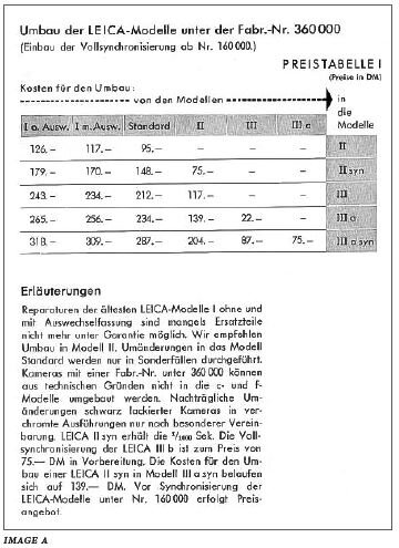
Image A
Let me translate part of the text below the table on image A. The table is valid for cameras with serial numbers above 160 000 and below 360 000. As a reminder, this represents what was available as of 1954.
“Repair and conversions of the oldest Model I’s with fixed and interchangeable lenses may not be possible any more due to the lack of spare parts, please ask for a quote. Upgrade to Standard as an exception only. Cameras with SN below 360 000 cannot be converted into IIIc, or IIIf. Chrome plating of black painted cameras on exception, please ask for quote. Cameras with SN below 160 000 require separate price quotation for adding synchronization.
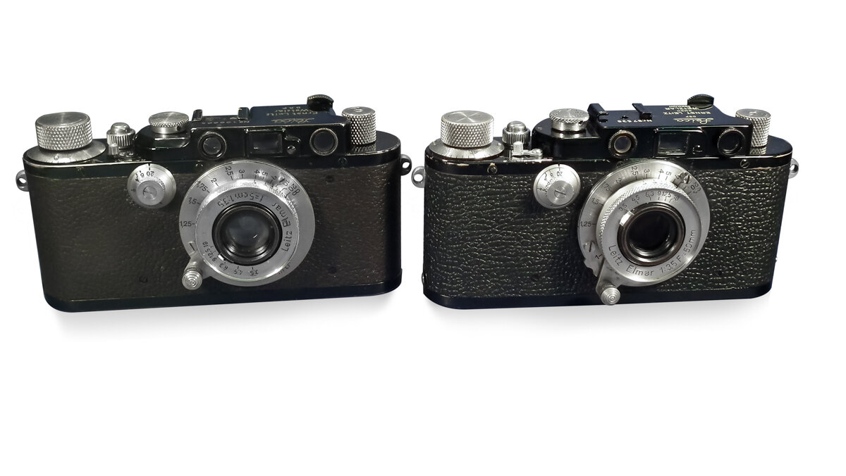
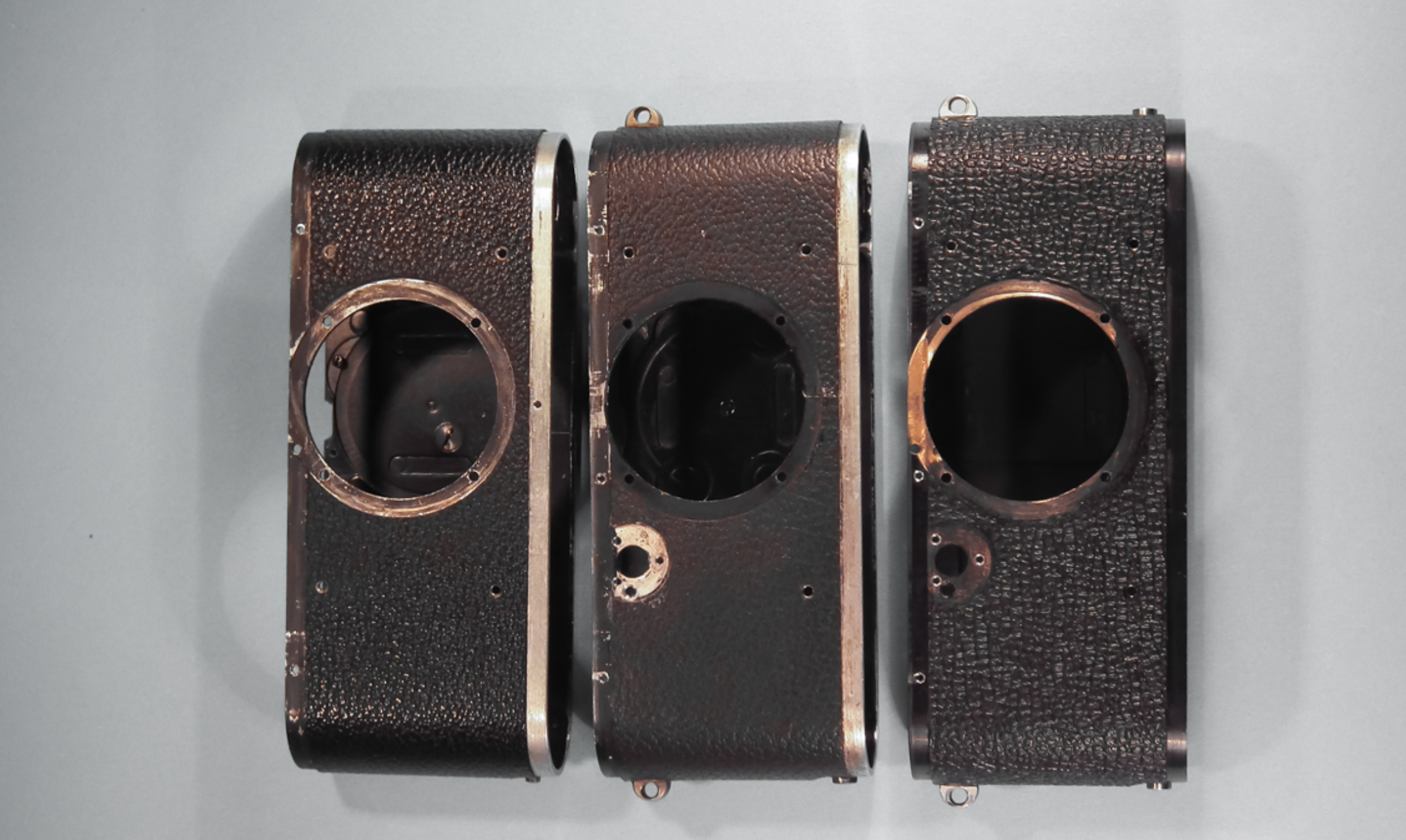
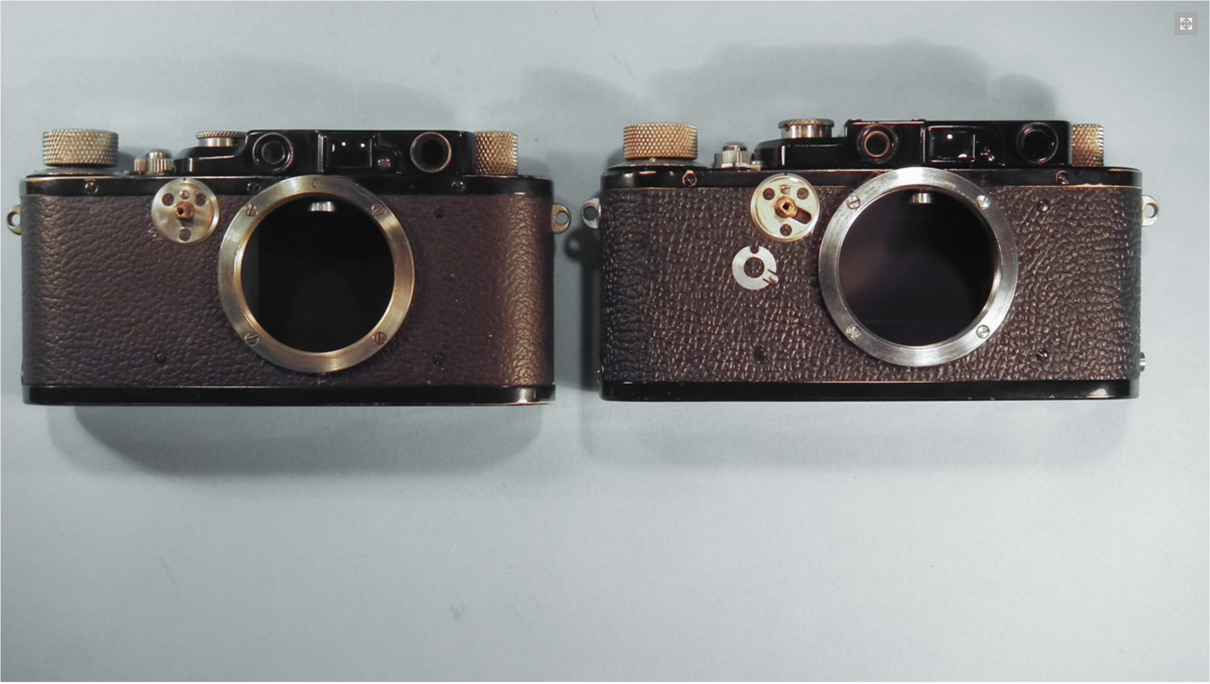
"Both converted cameras were originally Leica II (model D): the 106 664 from 1933 and 87 538 from 1932 [2], they are now III, or IIIa. Both are black painted with nickel plated knobs. Comparing the top covers we may notice that they look different. However more significant differences are hidden inside. (image 2)
Let us start with details which may be seen from the outside and under the top cover. Both cameras received a new shell during conversion. The reference camera has an inspection cover screw on the rear side and thin pin (3mm) for the bottom cover. Converted cameras do not have this screw cover anymore and the pin is thicker (4.9mm). Camera S/N 87538 has as well the second pin for the flash mounting bracket (although the camera itself is not synced for flash). The pattern of the Vulcanite covering on 87538 is like that on the production cameras from the fifties, while the Vulcanite of 106664 is like that on the cameras from the early 30’s. (images 3 & 3a)
New shells required new film pressure plates as well. On the left is the pressure plate from the reference camera; on the right are the film pressure plates from both converted cameras (image 4)


Similarly, because of the new body shells the bottom covers have been replaced. On the photo below we see the bottom covers from inside. Let me call your attention to the film loading instruction plate which is in German only and the square notch on the stiffening bar on the bottom cover of the reference camera. Both converted cameras have instructions in four languages. Engravings “zu“ and “auf “ on camera 106 664 are filled with bismuth, while the bi-lingual engravings on 87538 are filled with white paint. These details are similar to production cameras from the 30’s and 50’s respectively. (images 5 & 6)
The top covers on both converted cameras have been replaced as well. The reference camera has a top cover with the so called “lavatory seat” indent under the speed dial, and is also narrower in this area. Some components of the slow speed mechanism required more space under the top cover, therefore the indent is absent on both converted cameras, and on 87538 additionally it is wider in the area of the speed dial. Flash synchronization contacts required more space under the top cover; we do not see it on 106 664 (flash sync was available from Leitz from the early fifties). Framing of the viewfinder window on 106 664 with the “step” was kept on production cameras until 1937. Let’s look at the engravings on 87 538; “DBP”, “GMBH” and all lettering in capital letters. Leitz introduced capital letters in 1955 [3].


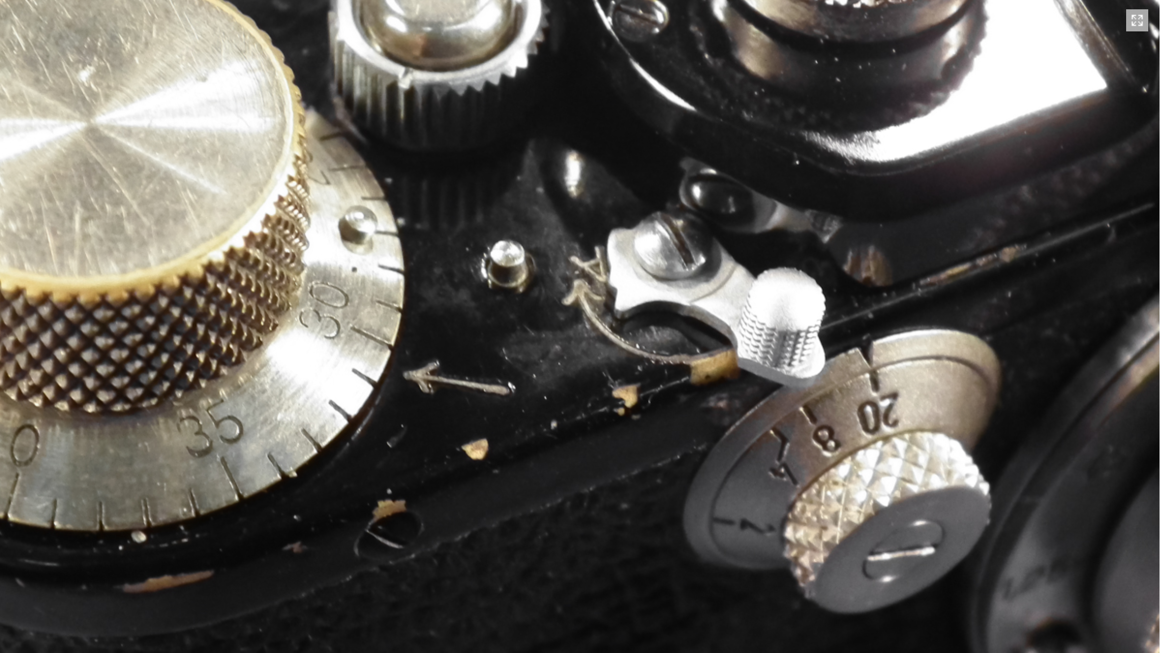
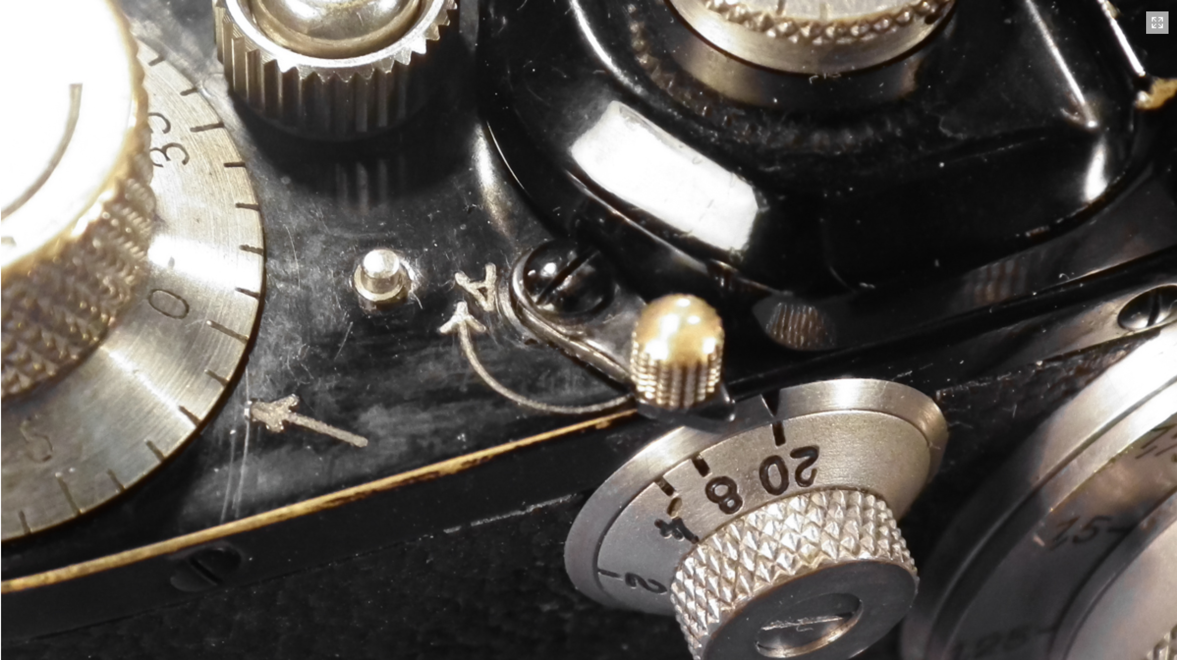


These details allow me to be more precise in dating the conversions: 106 664 not later than 1937 and 87 538 not earlier than 1955. (images 7 – 9)
With the new top covers, the speed dials have been replaced during the conversions as well. The original speed dial had a diameter of 15.5mm while both converted cameras have a 13.7mm diameter. On the camera 106 664, the speed dial is screwed on and fixed with one screw on the side, while on 87538 it is set on and fixed with 3 screws. This corresponds with the speed dials from the 30’s and 50’s respectively. (images 10, 10a, 10b)
The rewind lever of 87 538 received a sort of notch. This was necessary to protect against the accidental exposure of a frame during rewind; the shutter was released but both curtains remained closed. This improvement was introduced in production cameras around 1938. The rewind lever is chrome plated and is typical of production cameras from this time. Black painted cameras with nickel plated elements were produced until approximately the end of 1935; afterwards black painted cameras received chrome plated elements. Obviously Leitz did not decide to produce nickel plated rewind levers for converted cameras only.
The fact that the notch does not exist on the rewind lever of 106664 and it is black paint/nickel indicates that the conversion happened before 1936. (images 11 – 12)
The eye piece correction lever was introduced with the Leica III. At first the shape was as seen on 106 664, and from approx. 1938 like that on 87 538. (image 13)
Rangefinder. The left tube is now fixed with 2 screws and not screwed-in like that of the reference camera (left on the photo below). I could not find any thread in the body of the rangefinder and this indicates that the rangefinder was replaced during conversion as a complete set. (image 14)
The support located under the accessory shoe. In contrary to the reference camera and 106 664 where the support is a round ring, in 87 538 it is open at the rear. It is higher than the ring as well; therefore the accessory shoe sits higher now (see as well Photo 2), above the surface of the top plate. The cutout and higher support were needed to accommodate the flash socket. Although 87 538 does not have flash sync, Leitz used the same parts which were prepared for sync cameras. See as well the top cover on Photo 9 – it is the same as on synced cameras with the exception of flash contacts sync numbers engraved around the speed dial. (image 15)
The upper cover (Kameraboden) is still original on both converted cameras. Engravings are filled with bismuth. (images 11 – 12).
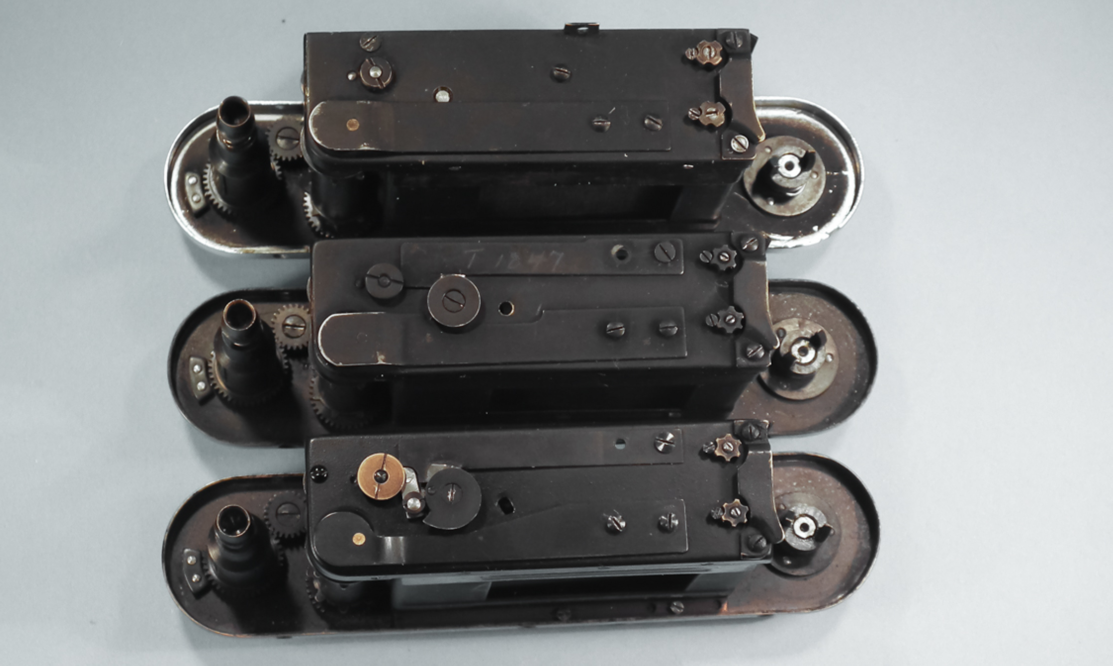
Additional holes have been drilled during conversion in order to accommodate additional parts and mechanisms. All other knobs seem to still be original, as they are nickel plated. Removing the bottom cover reveals further differences. First, the second leaf spring. It belongs to the slow speed assembly and is pressed down when the first curtain is at the end of its travel (fully open). The disc which is mounted on the axis of the curtain drum has a rivet. The disc rotates as the first curtain travels, and at the end of its travel the rivet presses the leaf spring down. On the camera 87 538, on the left side of the disc there is a lever which activates the curtain brake. (image 16 – top: reference camera, middle: 106 6645, bottom: 87 538)
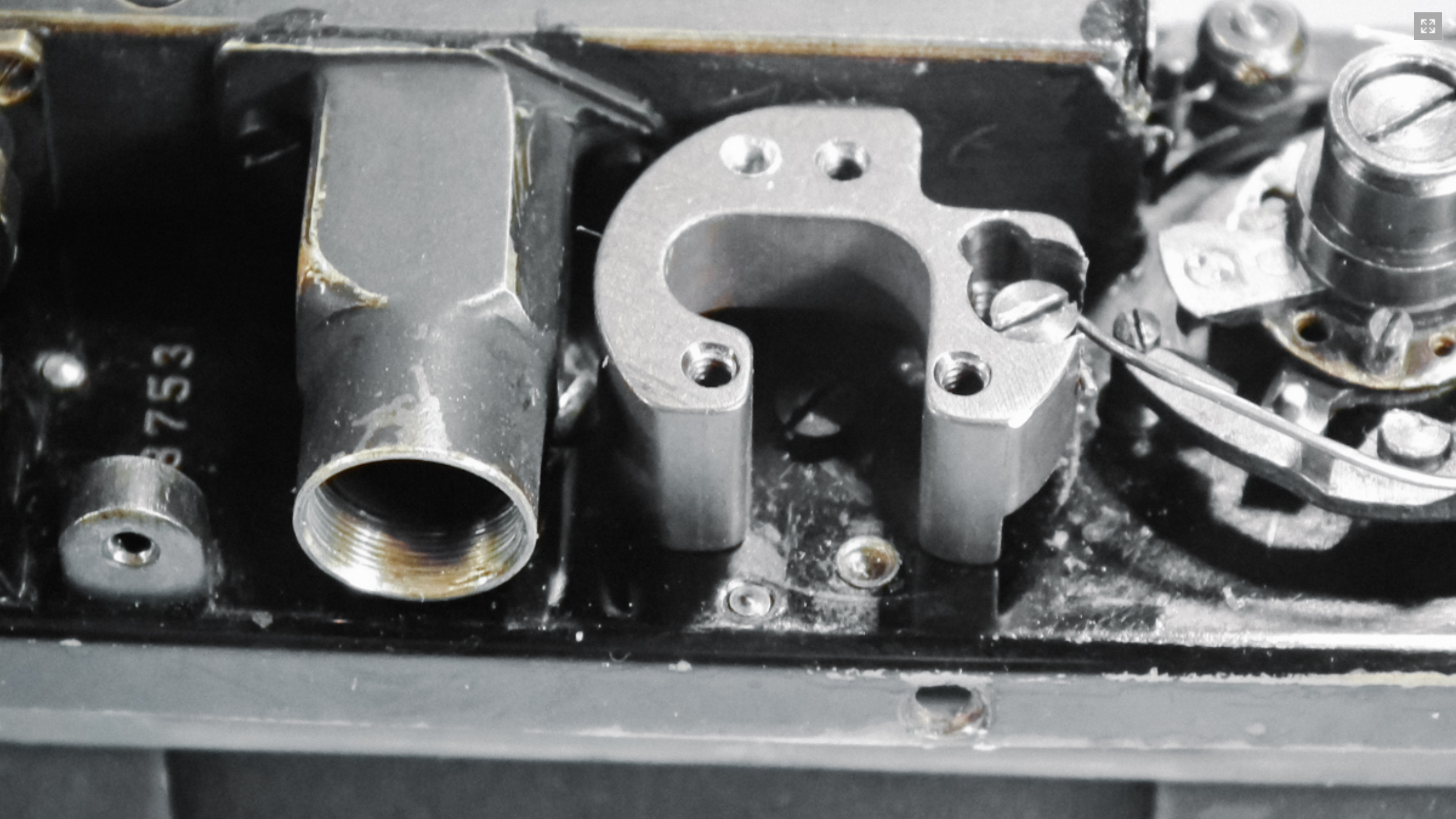

A short history about the curtain brakes in screwmount Leicas – Early cameras did not have any curtain brake. One of the gears coupled with the curtain drum and had a circular milling; below this gear there was a pin mounted in the camera crate (image 17). The milling was not in a full circle; it represented the start and end of the curtain travel. At the end of first curtain travel, the milling hit against the pin and the curtain was stopped immediately. Not very gentle and although the mass to be moved is not too much (curtain drum, two gears, speed disc and dial), such a rapid stop could lead to shutter bounce. In order to prevent this, the disc received a second modification. A semi oval notch on the disc pressed against the U-shaped spring at the end of travel (image 18). This type of brake was introduced around 1935. Further development was implemented in later wartime IIIc’s, and utilized a real drum brake. The drum brake is built into the gear where the milling in earlier cameras had been. Milling and stop pin were moved under the gear mounted directly on the curtain drum axis (image 19). The disc has as well another shape, when the first curtain is near the end of its travel, the disc gradually presses against the lever which activates the brake. The ring on the lever is eccentric and allows for more precise adjustment of the braking force and breaking point. Although this construction was introduced in 1940, the wartime IIIa and IIIb still had the spring brake. Some of the postwar IIIa’s and IIIb’s, but not all of them, received this newly-implemented drum brake.


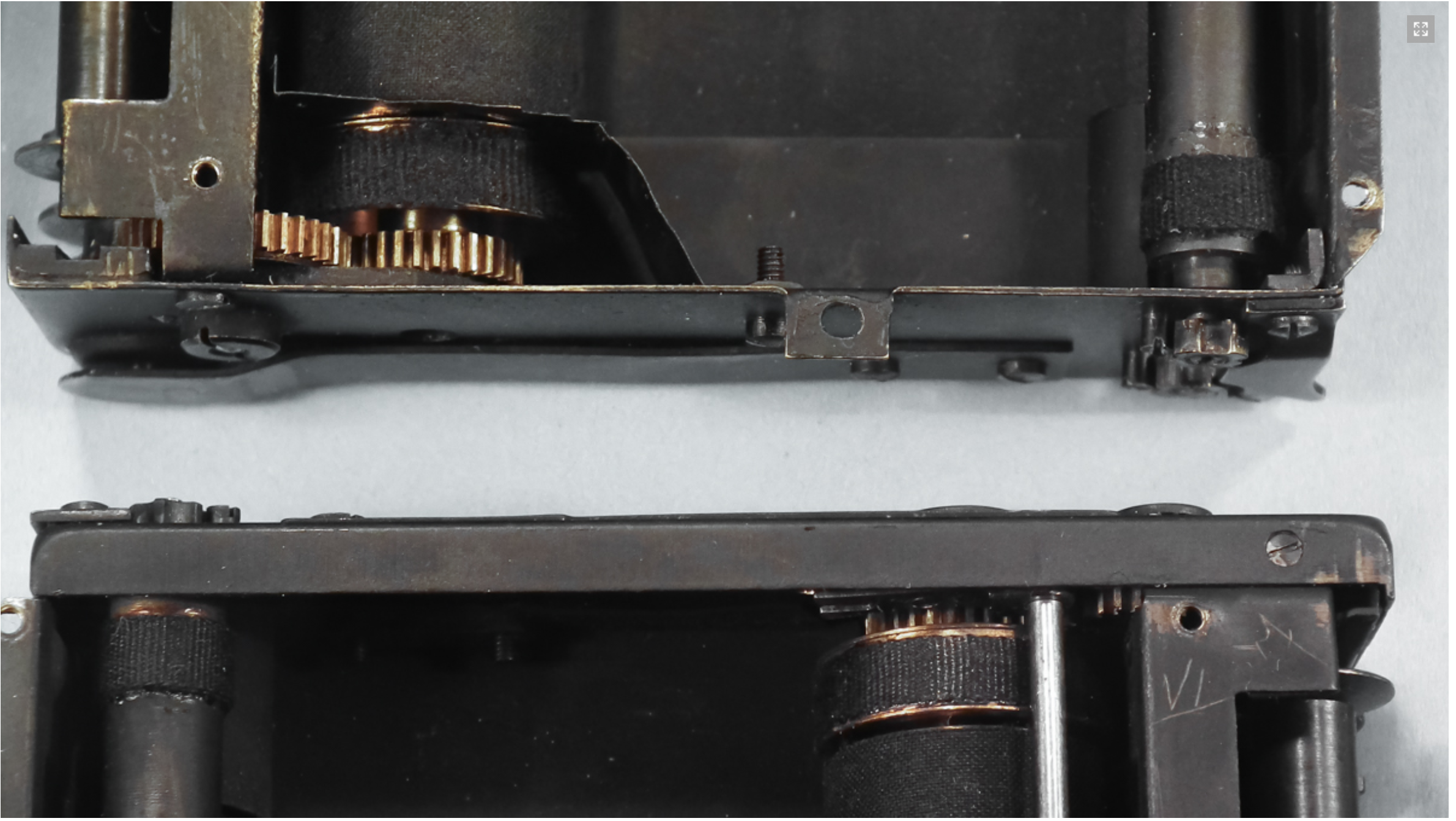

Camera 106 664 does not have any brake yet, this allows for further narrowing of the conversion time – before 1935. (images 17-19a)
Let us examine the shutter now. As mentioned above, the disc needed for slow speeds requires an elongated axis on the shutter drum. The axes of the small curtain drums (right in image 20) are thinner than in the reference camera and the lock nuts now have six lobes instead of four. This allows for more precise adjustment of the tension of the axial springs within the drums. Not shown here – the axial springs are different now with the converted cameras. They are moving not only the first and second curtain as in the reference camera, but the slow speed mechanism is also activated by the second curtain. The shutter module has been replaced during conversion. One of the smaller drums on camera 87 538 has as well a small gear in the lower part. This gear has no function in this camera, but in postwar IIIc’s it was used to reset the slow speed mechanism. Further evidence that the shutter in 87 538 had been replaced after 1946. (image 20)
The camera frame is shaped differently in both converted cameras. Do you remember what I wrote in the section about the bottom cover stiffening plate and the square notch in the reference camera? The camera frame is fixed to the shell with an additional screw, and a notch is needed to provide a place for this screw. The frames in both converted cameras have been replaced during their conversion. The fixing screw is no longer needed anymore; therefore the notch on the stiffing bar of the bottom does not exist (image 21, reference camera at the top)
The photos below show the cam follower rollers and levers which couple the lens distance setting to the rangefinder. The fact that the roller of 106 664 is painted black in the middle is of no relevance. Of interest however is the lever of 87 538 – I have seen this shape on IIIg’s only and because the IIIg was introduced to the market in 1956 it determines the earliest time for this conversion – not before 1956. (image2 22-24 from left to right: reference camera, 106 664, 87 538)
And finally the slow speed escapement. Obviously, the reference camera does not have it, as it is a Model II. However, comparing the slow speed gear trains from both converted cameras, the difference is visible. In 106 664, during return after being engaged all gears return to the start position. Th ey were moved by a small spring within the mechanism and the return usually took more time than its movement during exposure. So it was possible, especially with at the 1 sec setting, that when someone was too fast in winding and releasing again, that the mechanism might not yet have reached its start position, and thus the exposure time might be shorter than the 1 sec set. Additionally, some people found the noise generated by the mechanism during return irritating. A few months aft er the introduction of Leica III in July 1934 [4], Leitz switched this the mechanism to a roller clutch. A roller clutch detaches a large part of the gears during return, and the return was much faster and quieter. Th e roller clutch was built into one of the gears, and for this reason had to be bigger than before.


The fact that 106 664 has an early type of slow speed mechanism provides the ultimate evidence for the date of this conversion – not later than July/August 1934! (image 25-26)
The new type of slow speed mechanism also required a semi oval cutout on the lower light shield; photo 27 shows it. And because we don’t see overpainted brass in the cutout, I assume that Leitz no longer had the appropriate spare parts in the late fifties and modified the existing light shield rather than replacing it, as I have also seen in other cameras converted earlier. Th e old type of slow speed mechanism in 106 664 did not require a cutout, and I assume that it is still original. (images 27-28)
There are further differences between both converted cameras like lens flange (nickel plated on 106 654 and chrome plated on 87 538), construction of the front, left window of the rangefinder, the speed disc under the top cover (due to 1/1000 in 87 538), the locking spring under the slow speed dial (image 28) and coating of the Elmar lens (SN 133 304) on camera with SN 87538. These details however do not provide any further information with regard to the conversion date.
Based on parts found in both converted cameras, I assume that the conversion of 106664 happened not later than July/August 1934, and conversion of 87538 was not done earlier than 1956. Two almost identical models and so diff erent. Is it not interesting? Interesting as well is the upgrade of 87538 to model IIIa, without fl ash sync. Th e majority of postwar conversions were conversions to IIIc or IIIf synch.
In my next article about Leica conversions I will present a rather unusual conversion of a wartime IIIc; on that occasion I will explain as well construction differences between wartime and postwar IIIc’s.
Any comment and/or feedback is welcome!
Jerzy Wasowicz, Vienna – Jerzy.w@gmx.net
sources
[1] “Leica – Umbau, Vergütung, Instandsetzung”, 1954
[2] Paul Henry van Hasbroeck, “Das große Leica Buch”
[3] Dr. Michael Wagner, “Umbauten von Kameras mit Gewindeanschluss”,
25 Jahre Leica Historica
[4] Personal correspondence with Mr. Ottmar Michaely, Sep. 2015